 SNES/SFC EPROM Cart
^ Home
SNES/SFC EPROM Cartfor 27C010, 27C020, and 27C040
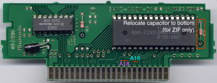
I recently found a SHVC-1A0N-01 SNES cartridge PCB (originally containing
Home
Alone) in the free area of a
Dallas retrocomputing meetup. Since my sister and I are currently working on
a SNES game, I thought I'd modify it to accept off-the-shelf EPROMs so I can
test our game on real hardware. Here is how you can make this mod too. This
tutorial is only applicable to the -01, but I'm sure the other 1A0N PCBs are
pretty similar. Note that this is a "LoROM" PCB (memory map
0x20), so only games using this memory mapping are compatible.
The mask ROMs used in SNES cartridges have a slightly different pinout than standard EPROMs. I'm using a 27C040 4Mbx8 EPROM because that's what I had on hand, but this should also work with the 27C010 and 27C020 with no changes, and the 27C080 with one addition. Here are the pin assignments we need to change:
| Cartridge pin | Function | Original mask ROM pin | EPROM socket pin |
|---|---|---|---|
| 42 | A16/BA1 | 24 | 2 |
| 43 | A17/BA2 | 1 | 30 |
| 44 | A18/BA3 | 2 | 31 |
| 45 | A19/BA4 | 30 | 1 (27C080 only, see note, otherwise just cut) |
| 49 | /OE | 31 | 24 |
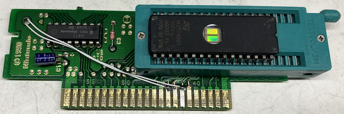
It should look something like this:
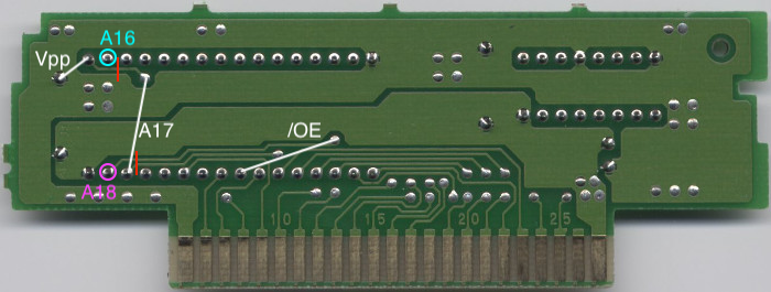
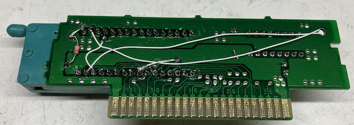
Now for the back. Here's what we're going to do:
Not the neatest thing in the world, but it works:
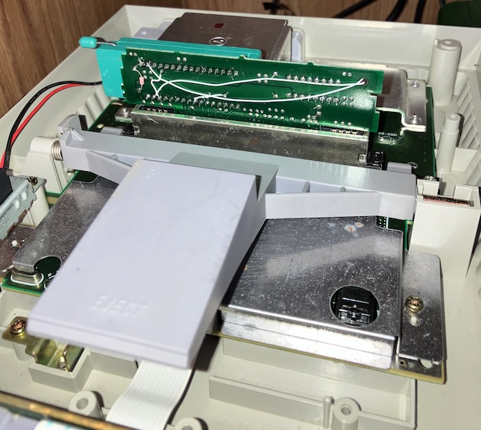
Now just burn your software to an EPROM and try it out!
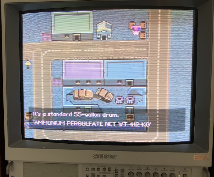
It works!
This should also work with the 27C080, but I don't have any, so I didn't try it out. The 27C080 uses pin 1 as another address line (A19) instead of Vpp. Instead of wiring pin 1 of the socket to ground, wire the via above socket pin 22 (this is cartridge pin 45) to pin 1.
Thanks to SNES Central for scans of the unmodified cart. Last updated 24 Aug 2024